
 10 December 2020
Telecommunication Systems and Cables
1 Introduction
The purpose of this article is to provide basic information on telecommunication, cables, and network equipment. This document is provided for reference only, actual training requires face-to-face meetings, demonstrations and practical applications.
2.1 What does Communication Mean?
Communication means sharing ideas, information and messages in a specific time and area. As a way of contact; communication includes visual communication like facial expressions, body language, images, photographs, or moving imagery. On the other hand, it can be electronic communication using telephones, internet networks, cable TV and satellite receiver. Communication is an essential part of human life and it has significantly reshaped learning, working, entertainment and daily life.
2.1.1 The Origin of Telecommunication
The word telecommunications is a combination of two words. TELE + COMMUNICATION The word TELE means distance in Latin. For this reason, Telecommunication means communication between two distant points. The need for telecommunication started with the existence of humanity on earth and the human need to pass information beside face to face communication and across very far distances.
2.1.2 Methods of Communication
- Using Primitive Sign Language
- Communication by making sounds
- Communication with smoke
- Communication with fire
- Modern Telegraph
- Telephone
- Communication with wireless network connection
- Communication via satellite
2.1.3 Requirements for Complete Communication
2.1.3.1 Source of News
The news you want to send consists of signs. These news can be sound, computer data, music, movie, temperature or alarm information. All these data are considered as messages.
- Messages can take many forms, such as human voices, music players, video players, computer or security systems messages.
- These messages, such as news, information, music players or audio signals, are converted into electrical signals depending on the type of message.
2.1.3.2 MODULATOR and TRANSMITTER
A message that can reach the desired point is sent via a transmitter. This message is converted into electrical signals in the modulator. The modulation process requires the original message or is the waveform of the signal at a low frequency. For this reason, it has low energy. Thus, modulation is the process of converting the original signal to a higher frequency signal than the original signal. Modulation is carried out in the device called transmitter. This process to be sent out is the conversion of the signals in the main source into appropriate signals.
2.1.3.3 CHANNEL
The scrambled signal is transferred from the transmitter to the receiver via a device called a channel. In communication, channel means a long transmission path. The variety of channels available today; cables, radio waves and light waves.
2.1.3.4 Receiver and Demodulator Receiver consist of successive transactions.
Receiving transmitter signals. Selection of the desired signal (mixed through the channel). Demodulation of the original signal to be reproduced.
2.1.3.5 Target of Messages
- The signal must arrive at the appropriate destination.
- For example, an audible computer signal may not be very useful. Or the value measured by a thermometer is not accurate.
- The target device must decide what to do with the signals. For example, receiving and storing signals or maybe directing the signals to another device.
- Successful communication happens when the original message arrives correctly at the target.
2.2 TRANSMISSION MEDIA
Communication networks provide distance determination of various transmission means, user information of the carrier, to satellite channels via copper cables. Transmission means is the physical path for the communication signal. Transmission vehicles can be classified into two main categories as wired and wireless vehicles. Wired vehicles may limit the communication signals, they guide but do not allow them to be transmitted. Radio vehicles, on the other hand, allow them to be transmitted. Metallic cables and optical fibers are examples of wire transmission means. Radio waves and satellite signals are examples of wireless transmission vehicles. An important characteristic of the two different devices is the bandwidth, or the open range at which each of the frequencies can be transmitted. Generally, a vehicle with a larger bandwidth transmits better.
2.2.1 Wire Vehicles
2.2.1.1 Metal cable
There are two types of metallic cables: pair cable and coaxial cable. While coaxial cable is better to be used in omnidirectional transmission applications, it is better to use pair cable at low speeds such as 1.5, 2 Mbits / s. Initially pair cables were developed for analog lines. Its use in digital transmissions, for example, in PCM links, is the limiting factor for interference between wires. Coaxial cable is used in FDM and TDM systems. Coaxial cable is characterized by its high bandwidth. This bandwidth provides it with high transmission capacity. For example, in the FDM system, transmission goes up to 10800 voice channels. Coaxial cable is used one for each direction in the form of a pair of wires. It is widely used among high density telephone exchange networks.
2.2.1.2 Fiber Optic Systems
Fiber optic is a rapidly developing transmission medium in telephone networks. The reason for this is that they have very good characteristics. Optical fibers have very good properties such as low weight, high bandwidth, lack of electrical conductivity, not being affected by electromagnetic environments and having low transmission losses. Fiber optic technology is developing as a very effective way to use it in new telecommunication applications. Fiber optic systems are widely used in cables used in smart buildings and local network connections of computer systems. Extensive research and development are carried out to make fiber optics more useful and economical.
2.2.2 Wireless Vehicles
2.2.2.1 Radio link systems
Radio link systems are a form of connection made through chains of receivers and transmitters. Radio links use both analog and digital transfers. Digital systems are fully designed for digital transmissions. Analog radio systems are used for the transfer of pulse-modulated signals. Each radio link connection needs two channels in each direction. The receiver and transmitter frequency are separated by a low Mhz. This is a very small difference considering the frequency band used.
2.2.2.2 Satellite Systems
Satellite transmission is similar in principle to ordinary radio link. We send information to space so that we do not have many stations on earth. Satellite communications speed is almost at the same speed as the earth rotates around its axis. Satellite systems have a fairly large range compared to radio systems and are used in national and international networks.
There are only a few problems with the transmission characteristics of satellite systems. The delays (reverb) caused by the long-distance transmission they have to do must be eliminated by the echo-supersor. It must be realized that this is the communication between two objects moving in space. The movements of the earth and the satellite relative to each other can cause errors in digital transmissions. However, these errors can be corrected thanks to intermediate storage in buffers. Since the first satellite was launched into space, the capacity of telephone channels has increased over time. While the first satellite Intelsat launched into space in 1965 had 75 duplex telephone channels, today the basic version of Intelsat VI can provide 80 000 telephone channels.
2.3 BASIC PRINCIPLES
2.3.1 Communication System
The first condition for basic information energy is to convert it from an electrical form (eg human voice, music or telegraph signal) to an electronic signal. This conversion is provided by the satellite transducer. The general definition of a transducer is that it transmits energy from one form to another and transmits it to a device.
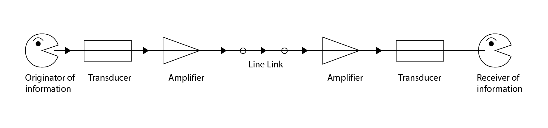 Figure 1. Basic requirements for one-way telecommunications channel. In a telecommunication line (figure 1), electronic signals are transmitted to the target by wire or cable link at a speed above 60% of the speed of light. At the target point, a second transducer converts the electronic signal to its original form. Amplifiers do not convert the signal, but increase the strength of the signals to compensate for the losses.
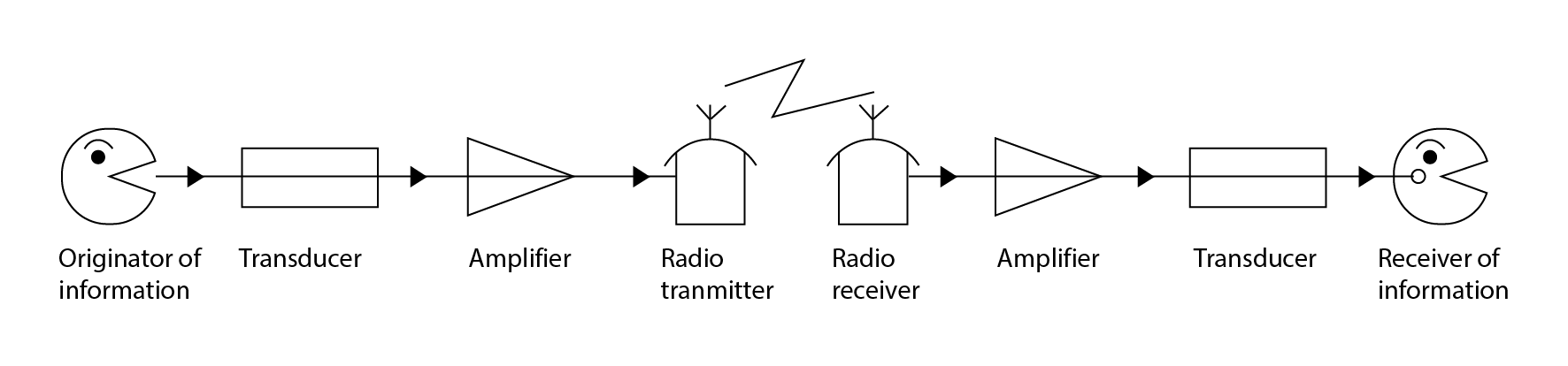 Figure 2. Basic requirements for a one-way radio telecommunications channel. In a radio system, a transmitter is required at the source to be able to send the signal over the radio link, and at the destination, a transducer is needed to recycle the signal before approaching the transducer.
2.3.2 Characteristics of the Radio System
When a radio frequency current flows through a transmit antenna, the power is dispersed in a number of directions, which is called an electromagnetic wave. The scattered energy reaches the receiving station in 5 different ways. (Figure 3)
- By surface wave
- With the sky wave
- With space wave
- Via a satellite
- With stacker
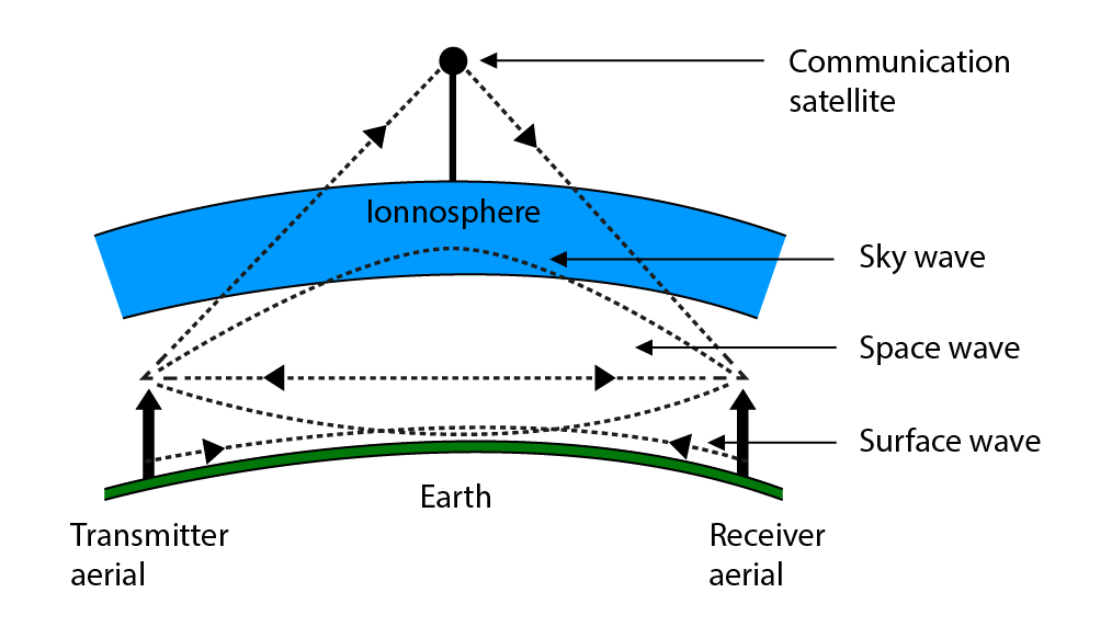 Figure 3 Radio propagation methods The surface wave is transmitted on the earth's surface at short distances from the ground and transmissions can be traced despite the earth's tilt. Surface waves are used in the low frequency band for worldwide communications and in the medium frequency (MF) band for radio and TV broadcasts. The sky wave is directed from the earth towards the ionshea (up to 100 km or higher from the earth) and is sent back to earth to be accepted in the desired area when certain conditions are met. Sky wave is used in high frequency radio communications, includes long distance radio transmissions and audio broadcasts. The space wave has two components. The first component refers to the transmissions in an almost straight line between the receiver and the transmitter, and the second to a singular reflection from the earth.VHF, UHF, SHF bands and high bands are also used in space wave sound and TV broadcasts, multichannel telephone sound systems, various vehicle systems. Communication via satellite is the reception of signals from the world to the satellite, their strengthening and sending them back to the receiver in the world at different frequencies. Communication satellites are used in the transport of multichannel telephone audio systems, television signals, data transfers and UHF and SHF bands. Stacking is the use of VHF / SHF equivalent sky wave transmissions for long distance HF radio lines. It is shown in Figure 4. Radio energy is directed towards the troposphere. These directed scattering signals are transmitted to the receiver. (The accumulation zone in the troposphere is about 10km above the earth.)Scatter systems are used to provide multichannel audio transmission links in UHF and SHF bands.
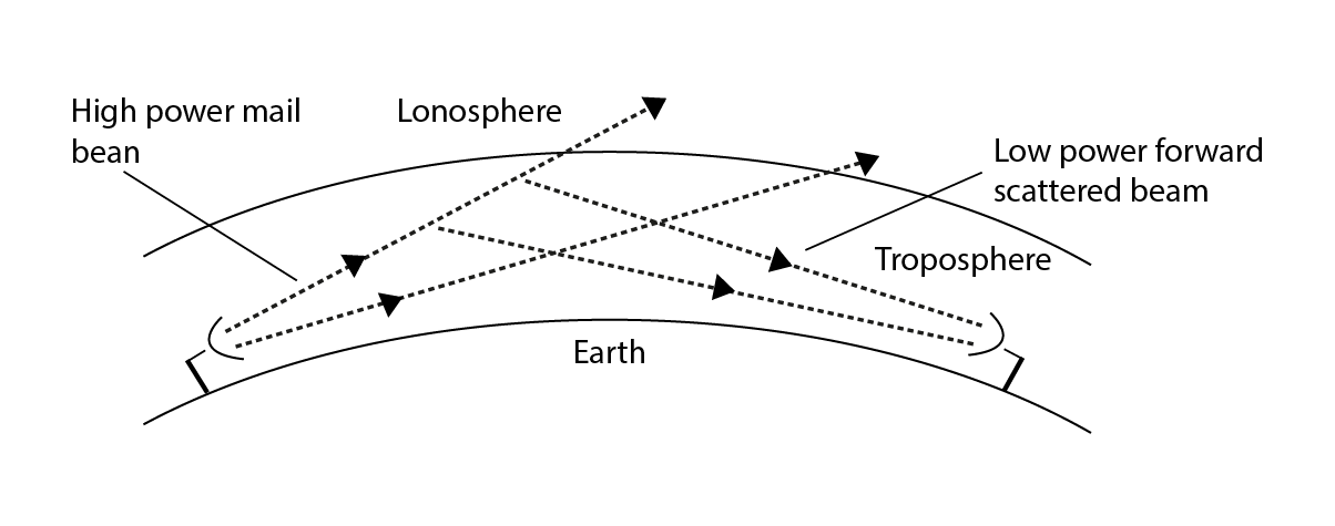 Figure 4. Demonstration of the satellite system
2.3.3 Radio Frequency Spectrum
Radio waves are measured in units called hertz (Hz). One rotation of the electrical current equals one complete radio wave. The radio frequency spectra are divided into a number of subsections. These sections are given below.
|
Frequency band |
Class |
Abbreviation |
|
Below 300 Hz |
Extremely low frequency |
ELF |
|
300 Hz-3 kHz |
Ultra low frequency |
ILF |
|
3 kHz-30 kHz |
Very low frequency |
VLF |
|
30 kHz-300 kHz |
Low frequency |
LF |
|
300 kHz-3 MHz |
Middle frequency |
MF |
|
3 MHz-30 MHz |
High frequency |
HF |
|
30 MHz-300 MHz |
Very high frequency |
VHF |
|
300 MHz-3 GHz |
Ultra high frequency |
UHF |
|
3 GHz-30 GHz |
Superhigh frequency |
SHF |
|
30 GHz-300 GHz |
Extremely high frequency |
EHF |
|
300 GHz-3000 GHz |
Enormous high frequency |
THF |
2.4 SIGNAL MODULATION IN COMMUNICATION
As explained, an early modulation signal is needed in communication because the actual audio frequency is not suitable for direct transmission since it will result in the use of long wavelength and unlikely antennas. Modulation is the process of converting sound frequencies to high level frequencies, and thus transmission is provided.
2.4.1 Module Types
The bandwidth required for radio-tv transmissions is 300–3400 Hz. For this reason, a connection is provided between the two parts, provided that there is one or two physical pair cables. Telephone cables, together with the ventilation ducts and the spaces of the ducts, are very expensive, but the two-point connection is the main part of the cost. Required from telephone cables; Providing multiple calls over a given line and being economical. If the number of telephone calls is completely sent to the end of a line, it is possible to separate it from the other end of the line since each conversation corresponds to the same part of the frequency band. How are many different conversations transmitted over a single translation and how are they separated at the target point?
2.4.1.1 Amplitude modulation (AM)
Amplitude variation (AM) and Frequency division multiplexing (FDM) are one way to solve the above problem. Each conversation is converted into a different frequency spectrum with a high frequency waveform carrying each speech signal. These high frequencies are called frequency carriers. Amplitude variation is the process of diversifying the sinusoidal wave amplitude carried by the amplitude of varying signals. Waves carried unchanged have a constant peak and a frequency higher than the changed signal. However, when the modified signal is applied, the instantaneous value of the changed signal and the peak value carried in a suitable variety and the contour wave vibration and the winding of the modified waves are the same as the actual modified signal waves. The altered signal waveform is superimposed with the transported wave.A carried sinusoidal wave (fc Hz) of frequency is the change in amplitude of the frequency by a sinusoidal change signal (fm Hz). The transported wave contains 3 frequencies. It is shown in Figure 6.
1) fc Hz: Original carried wave 2) (fc + fm) Hz: Sum of the signal frequency changed by the transported wave 3) (fc - fm) Hz: Subtracting the changed signal frequency from the transported wave
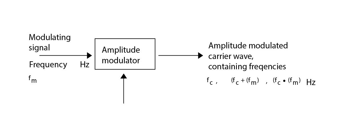 Figure 6 Amplitude modulation method
Two of these frequencies are called side frequencies, they are new and are generated by the amplitude change process. The sum of the signal frequency changed by the carried wave is called the high side frequency. Subtracting the changed signal frequency from the transported wave is called low side frequency. The frequency spectrum diagram is shown in Figure 7.
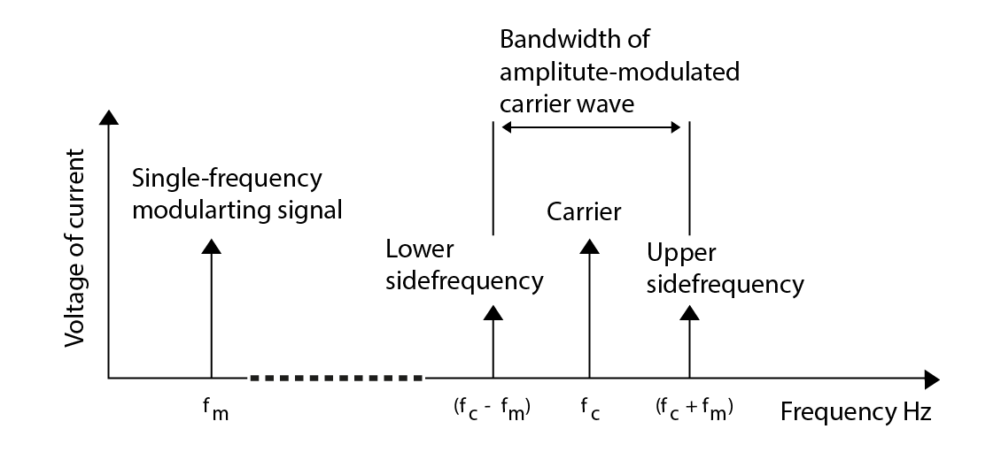 Figure 7. Frequency spectrum of an amplitude modulation wave for a single frequency modulation signal.
The bandwidth of the transported wave is (fc + fm) - (fc - fm) = 2 fm. An example is the double-changed signal frequency. The bandwidth of the amplitude modulation carrier waves is obtained from the sum of the low side frequency and the high side frequency and is shown in figure 8. This carrier wave obtained has a larger bandwidth. All information is carried by a single sideband fm and the resulting carrier fc is larger than is actually needed in terms of information signal transmission. The carrier consists of amplitude and frequency and cannot carry all of the information signals. This is possible by stopping the carrier and single sideband by using special equipment and transmitting the other sideband without loss of information. This method is called single sideband study.This method cannot be used in local radio broadcasts, but is used in some long distance radio voice transmission systems and multi-channel carrier systems in national telephone networks.
2.4.1.2 Frequency Modulation (FM)
Another method of adding information signals to carrier signals is frequency modulation, which changes according to the modulation frequency of the carrier wave. Frequency modulation has more advantages over amplitude modulation (AM). Frequency modulation is used for audio broadcasts in the VHF band and for the audio signal of 625 line TV broadcasts. It is also used in the VHF band for some vehicle systems and for multi-channel audio transmission systems. Frequency modulation is used in analog communications through satellites. Frequency modulus has a larger bandwidth than AM. A sinusoidal carrier wave causes the instantaneous frequency to change in accordance with the modulation signal character when the frequency is modulated. The magnitude of the change (known as the frequency deviation) is the proportional amplitude of the modulation signal voltage.As shown in Figure 9, when the modulation signal becomes a sinusoidal waveform, the modulated transported wave frequency will turn into sinusoidal.
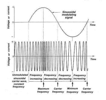 Figure 9. Frequency modulation carrier waves The frequency deviation of a frequency modulation carrier wave is the proportional amplitude of the modulation signal voltage.
2.4.1.3 Pulse Modulation (PM)
Another method of transmission of information is by means of pulses of voltages or currents. The wave carried by pulse modulation is not sinusoidal but consists of repetition of right-angle pulses. As shown in Figure 10, the amplitude, position or width of the pulses can be changed via the information signal. Pulse amplitude modulation is a form of modulation in a pulse duration. This modulation is appropriately converted into a modulation signal. Sometimes width pulse modulation is also called duration pulse modulation or long pulse modulation. Pulse shape modulation, which is a modulation type, is converted into a suitable form of modulation signals in the pulse duration without changing the pulse width.
2.5 EVOLUTION OF TELEPHONE CABLES
Alexander Graham Bell invented the telephone 100 years ago. Initially, the phone lines were split to connect phone pairs. Each time he had a phone, he could only talk to another phone. The first telephone line was established in Boston in 1877. This line connected Charles Williams' home in Somerville MA with his office in Boston. The use of personal lines was very limited at that time. People wanted to be able to talk to more than one person and there was a need for a hub where telephone lines could be connected to each other.
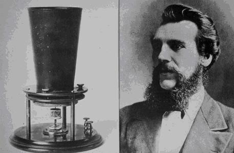 Alexander Graham Bell and Telephone The first telephone lines were the lines that went over the ground, that is, through roofs or telephone poles. Telephone lines were cables made of single grounded iron or steel. Although some cables are galvanized for corrosion resistance, corrosion problems have not been completely eliminated. Lines were single grounded and naturally interfered. Phosphor bronze cables and copper composite steel cables were produced in order to reduce the interference in the lines. The use of copper-component cables was known to be beneficial, but it was not possible to produce copper cables of sufficient strength for the lines passing over the ground at that time. In 1877, Thomas Doolittle produced rolled copper cable in the Naugatuck Valley region of Connecticut. He passed his soft annealed copper cable through a series of rolling mills to increase its tensile strength.Rolled copper cables had enough durability to be run over the ground, and telephone faults also replaced the cables used. In 1884, experimental copper telephone lines were established between Boston and New York. In 1885, a line of rolled copper cable was established between New York and Philadelphia. Many manufacturing companies started production to meet the increasing demand for rolled copper cables. The use of rolled copper cables has been extended by its use in power transmission lines and in the electrical industry. The metallic circuit and the double wire circuit were developed and patented in 1881 by Alexander Graham Bell. Metallic circuitry was a significant improvement because it prevented unwanted noise in the cables and transmission disturbances.The establishment of metallic circuits brought with it physical and financial problems. All lines passing over the ground were gradually replaced between 1890 and 1900 with grounded double-wire lines. The benefit of this change was that the line was insulating and allowed the cables to cross. The development of telephone cables is interesting. A single telephone cable contained many telephone wires. Better insulation brought the need for electromagnetic and water resistance. The technology of the first telephone cables also forms the basis of the production of telegraph cables. Gutta percha and rubber-based materials were first used in telegraph and telephone cables to increase insulation and water resistance. After 1879, telephone cables were used under water, on the ground and in antennas.New cables produced in 1887 were cables with metallic circuits. The first telephone cable implementations were carried out on the West River bridge, under the North River between New York and New Jersey, and on the Delaware River between Philadelphia and Camden. Cables manufactured by different companies were similar but not identical. The cables consisted of up to 100 copper wires. The insulation of the cables was achieved by covering the cables with cotton, paraffin-containing cotton, gutta percha and rubber-based materials. Cities also needed to replace huge quantities of antenna wires with telephone wires, which led to an increased need for telephone wires. In the 1880s, the main areas of interest for telephone wires were noise removal, water resistance, and multiple wire connections in a single cable.The coated conductive wires inside the cables were developed by removing the electromagnetic sounds in the lines. Other insulating techniques are covering the material with thin foil and increasing the insulating material layers. In the guide tube techniques developed after the conductive wire, melted paraffin, fennel, fennel paraffin mixture and tested oils were used by rubbing them from one end to the other in the tube to protect the moisture from the insulating property. Towards the end of the 1980s, telephone and electrical power cables were laid underground in a channel made of wood. After that, glazed clay channels were developed. Multiple closed channels used formed the basis of underground pipelines.Separated square spaces were provided for each cable, and more closed conduits were needed to add conduit sections.
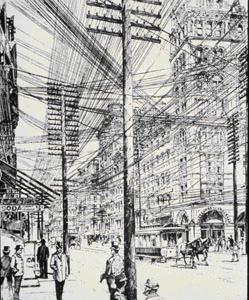 A view of Manhattan Street in the 1890s. Poor voice transfers over telephone cables, unidentified sounds, muffled voices and echoing were still unresolved issues. Two major improvements were made to telephone cables in the late 1880s. The first improvement was made in 1888 with the publication of a requirement for standardization of telephone cables. In the specification it was stated that there should be a metallic circuit or two pairs of wires. The cables consist of copper conductive wire, 18 B&S in diameter (40 miles in width), covered with at least two layers of cotton, placed in a pipe consisting of 97% lead and 3% tin alloy. The spaces in the center of the cable and between the center and the pipe are filled with insulating material. A 2 inch diameter cable contained up to 52 pairs of wires.The second improvement was made by using dry insulating papers at the center of the cables. The use of dry center cables was successful because the resistance to water was increased by the use of lead-tin alloy sheath dry core cables. The size and electrostatic capacity requirements of the conductors in the lines have been greatly reduced and the sound transmission has been increased to very good levels. Improvements in continuously produced telephone cables; The use of better and more insulators in the cable, the need for low electrostatic capacity and the creation of more gaps for papers used for insulation. Some of the cable improvements made were effective in the sound transmission field. For example receivers, transmitters,He was instrumental in the development of coils and telephone exchanges. The next big step is the establishment of telephone lines, thus increasing efficiency in transmission. In 1912, an alloy containing 1% antimony and 99% lead was developed for use in telephone coatings. This alloy was more economical than a lead-tin alloy and had better mechanical properties for the antenna and underground cables. In addition, this material had good stress resistance and corrosion resistance. Another improvement is the invention of the amplifier. The amplifier repeats the audio signals. Carrier systems or multi-part single pair cables were used in versatile searches.An alloy containing 99% lead was developed. This alloy was more economical than a lead-tin alloy and had better mechanical properties for the antenna and underground cables. In addition, this material had good stress resistance and corrosion resistance. Another improvement is the invention of the amplifier. The amplifier repeats the audio signals. Carrier systems or multi-part single pair cables were used in versatile searches.An alloy containing 99% lead was developed. This alloy was more economical than a lead-tin alloy and had better mechanical properties for the antenna and underground cables. In addition, this material had good stress resistance and corrosion resistance. Another improvement is the invention of the amplifier. The amplifier repeats the audio signals. Carrier systems or multi-part single pair cables were used in versatile searches.
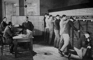 Telephone switchboard operators The telephone industry entered a period of rapid change and development in the late 19th century and early 20th century. Some of the recent developments are the use of plastic in insulation and the development of coaxial cable during the second world war. Up to 600 conversations could be transferred with two coaxial cables. Today, with the development of telephone cables, more information can be transported at higher speeds over the same line. One of the interesting developments is the development of ADSL (asymmetrical digital subscriber line). ADSL is a transmission path through which a lot of information is sent in a robust way with an ordinary copper cable. ADSL transmission technology has potential voice, data transmission. It also has up to 4 video channel subscribers and data transfer rates up to 8 Mbps.Copper telecommunication cables are used for voice and data transmission in telephone companies. Telephone cables have come a long way since 1877 and its technology is still being developed.
3 FIBER OPTIC CABLES
Fiber optic cables basically consist of standard fiber optics, buffers, resistors and sheaths. The coating of fiber optics is done with a thin film. This coating protects the fiber from external corrosion as well as from internal reflections. The buffer zone allows the flexible movement of the glass fibers during abrasion caused by the braided resistive elements consisting of a dispersed tube or taut pad. The periphery of the buffer zone is mostly covered with kevlar-containing resistance elements. This zone provides mechanical resistance to the cable and prevents excessive stretching of the fibers. The outer surface coating of the cable is made of a polymer-based material to protect it from tearing and abrasion.
3.1 FIBER OPTICS
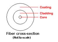
A fiber optics standard thickness is about one strand of human hair. Fiber optics are designed to convey information using pulses of light emitted from a laser. Although fiber optics may seem relatively simple, they are actually complex structures. It consists of 3 layers.
|
- Core: It is the glass in the center of the fiber and light pulses pass through this region. - Cover Cladding: It is the glass scattered around the core and catches the lights escaping from the core. - Outer layer: It consists of a double layer with a soft substrate. While the soft layer acts as a cushion to the glass fiber, the outer layer gives it hardness and handgrip. |
 |
|
The core and sheath are made of very pure glass, but the sheath layer consists of even more pure glass than the core. The reason for this is that when fiber is produced, a substance called dopant is added to the glass in the core to change the basic properties of the light. This difference in property between the two glasses serves to keep the light pulses in the core. |
|
 |
(Although the center is not hollow) Tunnel produced for light transmission; When the light inside the core and the glass in the sheath affect each other, it acts as a reflection for the light to return to the core. This principle is called total internal reflection. With this principle, the light trapped in the core is kept and the light inside the fiber is allowed to pass through the bends. With this method, light signals can be transmitted over a distance of over 100 miles without support. |
|
Information is carried in the fibers by pulses of light. The fibers use a binary code (on-mode-off mode) to determine what kind of information the signal contains. This situation is similar to Morse Codes, and each series of pulses corresponds to a letter in the alphabet. However, thanks to pulses in fibers, video, audio and computer data can be transported depending on the type of transmitter and receiver used. How much information is transported by fibers is explained as follows: A single laser can be turned on and off at values close to millions per minute, and a single standard glass fiber can also carry multi-wavelength light (different colors). These are the quality of fiber optic sets from other communication technology, and nothing else comes close to the information carrying capacity of fiber optics. |
|
3.2 SINGLE MODE AND MULTI-MODE FIBERS
There are two types of fiber optics, single mode and multi mode. Multimode fiber has a wider core than a single mode fiber, thus enabling hundreds of light beams to pass through at the same time in multimode fibers. Single-mode fiber has a very small core and allows only one type of light to pass through its core. While multi-mode fibers seem to have more information-carrying capacity, the opposite is actually true. Single mode fibers can transmit a lot of information over long distances by using each light pulse without wasting. This high bandwidth indicates that single mode fibers are the ideal transmission medium for many applications. Nowadays, multimode fibers are used as a precursor when transmission distance is less than 2 kilometers.
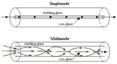
The difference between fibers; It is the difference in core sizes and light transport regions of the cores. Single-mode fibers have a core diameter of approximately 8–10 micron meters. The high information carrying capacities of single-mode fibers are generally used in long-distance and high-band innovation applications. Multimode fibers have cores of several different diameters. Commonly used diameter sizes are between 50 and 62.5 micron meters. Thanks to this high diameter size, multimode fibers have better band regeneration and are easier to pair and interconnect.
3.3 BUMPERS (BUFFER TUBES)
Manufacturers use various techniques in fiber optic buffers. Types of fiber pads include loose tubing and tight cushioning. The choice of buffering techniques depends on the intended application. Loose tube buffers are used in commercial applications and tight buffers in non-commercial and marine applications.
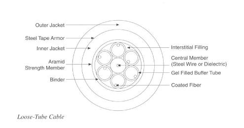
3.3.1 Loose Tube Cable
The design of the loose tube cables consists of a red coded plastic buffer tube and fiber optics, and by filling a gel, water ingress is prevented. The increased fiber length (according to the buffer tube length) prevents the pressure from their assembly and external factors. Buffer tubes are a wire made of central steel covered with insulating material and protect the fiber against bending. Cable core is covered by aramid thread. This yarn is the primary tensile strength element. It is wrapped around the core by an outer polyester sheath. If armor is needed, a curved steel variant is wrapped around the single case with the sleeve attached to the armor. Loose tube cables are used on the outer surfaces of antennas, ie open areas, ducts and underground applications.
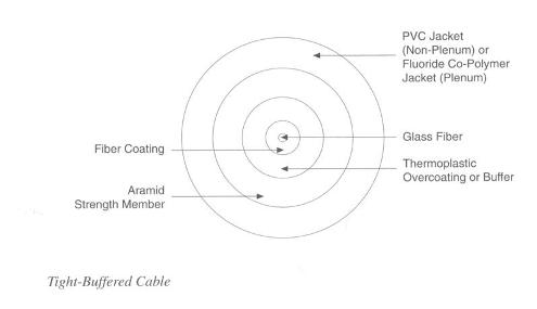
3.3.2 Tight Buffer Cables
With Tight Buffered cables, the buffering material is in direct contact with the fiber. These cables are suitable for the connection of outdoor cables (jumpers) in terminal elements and in the connection paths of building networks. Multi-fiber, tightly buffered cable is mostly used indoors, stepped platforms and ordinary structures. The tight cushioning is designed in a robust structure to protect each fiber from external influences when handled, used in turns and used in connections. As with loose tubes, the properties of tightly buffered cable may not meet the standards, although cables of all fibers contain maximum performance in terms of strength in high temperature applications.
3.4 CABLE RESISTANCE AND SUPPORT ELEMENTS
Fiber optic cable strength elements are used to increase the strength of the fiber optic cable. Fiber optic cables can be used as basic support elements in cable production. Power plant support elements are usually helically cushioned on the surfaces of the cables in fibers or single fiber cable infrastructures. Switchboard elements can be used as resistance elements in fiber optics like filling materials or only as auxiliary elements. Resistance and support elements should be light and flexible. Commercial applications use materials containing steel wire and textile fibers (such as nylon and aramid yarn) for strength and support. These materials also include carbon fiber, glass fiber and reinforced glass fiber. Only metal-free support and resistance materials are allowed in marine applications.
3.5 CABLE SHEATH MATERIAL
The sheath is very environmentally friendly and provides mechanical protection. Sheath materials in marine cables have the following features:
- Low smoke generation
- Low toxicity
- Low halogen content
- Flame resistance
- Fluid resistance
- High wear resistance
- High performance in extreme temperature applications
It is difficult to produce a high-composition material at low cost for every need. Initially, fireproof cables were produced from halogen polymers and derivatives of halogen polymers, and these cables contained highly toxic substances. Commercial jacket materials currently include polyethylene, polyvinyl chloride (PVC), polyurethane, and polyester. Commonly used commercial covers are not suitable for tanning.
3.6 CABLE DESIGN
Manufacturers design optical fiber cables for specific applications. It is difficult to agree on standard cable design. In cable design, sheath materials, water prevention techniques and the number of fibers used in the cable constitute the design criteria. Cable design is made according to where the cable is used and many types of cables are designed today. Some fiber optic cables are used in military applications, while others are used in commercial applications. Production of standard fiber optic cable depends on the development of fiber optic technology. Some cable designs are given below:
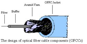
3.7 FIBER OPTIC CABLE COMPONENTS (OFCC)
An OFCC cable consists of single fiber optic cables and is called fiber optic cable components (OFCCs). OFCCs consist of a low halogen outer sheath and a tightly buffered fiber surrounded by aramid yarn. OFCC's outer diameter is usually 2 millimeters. The fiber is usually buffered with a polyester with a total diameter of 900 microns. Its design is shown in the figure below. The limit of the size of OFCCs is determined by the number of fibers in the OFCC cable. An ordinary OFCC cable contains less than 36 fibers (OFCCs). An OFCC cable with an outer diameter of 0.5 may contain 12 fibers.
 Representation of fiber optic cable components. The isometric view of a quadruple fiber optic cable is given in the figure below. In this multi-cable design, a flexible core element is wrapped around fiber optic cable components (OFCCs) in a helical structure. The central element can increase the strength of the cable or can only be used for support to OFCCs. For strength purposes, OFCC cables are covered with double layer aramid yarn resistance elements. These resistance elements keep the small bending of the fibers to a minimum. When aramid yarn resistance elements are processed with polymers, they are very successful in water absorption, impermeability and resistance to water. Material selection with this feature is made in cases where protection against water is required. Finally, the outer surface of the resistance elements is low halogen,It is covered with fire-resistant sheath.
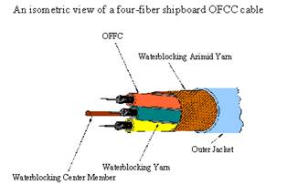 Isometric view of a quad fiber optic cable OFCC cables are easy to process because each cable has its own sub cables. Sub cables make the system easy to rearrange and each fiber can be handled on its own. The robust OFCC cable design allows the cable to be used easily in harsh conditions, including marine applications. OFCC type cables are recommended for use in low density (less than 24 fibers) marine applications, and cables containing 36 fibers at most are used in marine applications.
3.8 TWISTED CABLE
Twisted cable; It is a fiber optic cable in which the fibers buffered towards the center are twisted and stretched in a twisted manner, their surroundings are covered with resistance material and the outer surface is covered with a protective sheath. The sectional view of the twisted cable is given below. The fiber is usually buffered with a polyester with a total diameter of 900 microns.
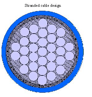
Braided cable design grows with increasing number of fibers without increasing cable size. Braided cables are used in cases where the fiber number of OFCC type cables is exceeded. For example, the twisted cable design can accommodate approximately 48 fibers in a 0.5 inch cable. OFCC cable knows up and down at 12 fiber bars. Each fiber in twisted cable design cannot be kept as well as in OFCC design. The main problem in twisted cable design is to ensure water resistance.
3.9 Ribbon Fiber Optic Cables
Ribbon cable; It consists of fiber optic strips in twisted form descending towards the center, a protective tube surrounding the cables, resistance elements and an outer sheath. Fiber optic strips consist of multiple layers of fibers with a diameter of 250 microns tightly packed into a plastic. Cable manufacturers stack the strands with the cross-sectional view of the fibers in a rectangular array as shown in figure b. The stacked strands form the basic structure of the ribbon cable. Manufacturers suggest that the stacked straps work like a dual protection mechanism when the cable is crimped. The inner plastic, resistance elements and protective cover envelop the stacked strips and protect them against environmental influences.
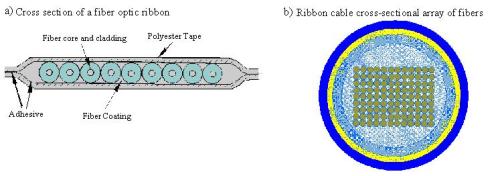
Ribbon cable design has very high fiber capacity. Ribbon cables can contain 204 fibers in a 0.5 inch cable. However, the flexural property of ribbon cables is worse than OFCC and twisted cables. Of the three cable designs, ribbon cables are the weakest in terms of water resistance. A decrease in bending performance is expected if suitable compositions are added to increase water resistance performance. Ribbon cables are difficult to process. When each fiber is separated from the ribbon cable, it causes high precision damage. This damage during the separation of the fibers causes the cables to have a need for multiple fiber connections. Multiple fiber connections can introduce single point faults in multiple systems and also cause reshaping and repair problems in terms of the consequences of using multiple fibers.
4 COPPER CABLES
4.1 GENERAL INFORMATION
Two main types of cables are used today:
- Double cables
- Quad cables
The choice of cable types is determined by various countries and depends on the standards of telephone systems. We can find the simple shape of the double wires in our homes. This cable has only two conductors and connects the plug to the phone. Operators have more choice than warehouses have. 2-, 10-, 50-, 100-, and 500-pair cables can be given as a few examples. Network access between subscribers and telephone exchanges, connections of some distances, telephone central and telephone lines are the main usage methods of double cables. Pair cables are mainly developed for analog connections. The large number of existing cable networks still consist of paper-insulated cables. Plastic is a better insulating material.Because plastic is not affected by moisture and has low power loss at high frequencies. This explains why new products are produced from plastic insulated cables. Most of the double cables are used underground.
 Figure cross-section view of double cable Generally, conductive materials are copper and conductive wires are produced in certain standard diameters. Common standard diameters are 0.4–0.5, -0.6, and 0.9 millimeters. The wires inside the cable are doubled by two conductors or four conductors.
 Figure: Two types of quad cable and double cable The cable core is often covered with paper or plastic consisting of one or more layers. This is to hold the cable pairs together and protect the cable. Cable sheaths are made of plastic, metal (lead or aluminum) or plastic and metal It is produced from foil composition. With proper material selection, the case can protect against electrical and magnetic environments. Further protection against mechanical damage is provided by armoring the sheath with steel wire or wrapping it around with a strip. More detailed information on cable core and cable structure will be given in the next section.
4.2 STRUCTURE OF COPPER CABLE
A typical telephone cable is made of a twisted pair metal conductor for signal transmission. Each conductor is insulated with a polymer based material. The desired number of transmission pairs are collected in the cable core in circular form and protected by an armored sheath made of metal foil and / or metal cable and polymer content. The sheath protects the core against mechanical and environmental influences. A core can be shaped similarly to a single core, which is usually found in a twisted pair. For example 50, 100 pairs. Larger cores can consist of up to 4,200 twisted pairs of wires. Simply the cable structure is as follows.
4.2.1 Conductive Material
A pure solid is wrapped around the annealed high conductivity copper wire, softly drawn to certain diameters (usually 0.4mm 0.5mm, 0.6mm and 0.9mm) and resistance is given.
4.2.2 Insulation
Each conductive layer is insulated with either medium / high density polyethylene (PE) or PE insulators in the form of foam. In order to assist the cables during the transmission of electricity and information, they are insulated with materials of various colors determined at very small tolerances.
4.2.3 Twisted Pair of Wire
Each insulated conductor is twisted together with the regularly prepared wire pair. Since the cable encounters problems such as resistance imbalance, loss of power, noise interference, the length of each pair of wires prepared is different from the next wire pair.
4.2.4 Cable Installation
The standard of twisted wire pairs consists of a single unit of 10, 20 and 25 groups, and these groups are spirally wrapped with bindings of certain colors. For higher cable pairs the number of groups is standard, consisting of 50 and 100 groups. The volumes whose colors are determined are wrapped around the groups for easy distinction.
4.2.5 Self Dressing
Groups of 50 and 100 are brought together to form the core of the cable. During this process, the gaps in the core are filled with insulating material to provide waterproofing. This material has a gel-like consistency, providing resistance to electricity and moisture between layers. The cable is then wrapped with a non-hygroscopic polyester layer to compact the gel-like filler.
4.2.6 Aluminum screen
The aluminum screens used in the cables provide both a liquid-moisture barrier and an electrical cage to protect the cable from external factors.
4.2.7 Inner Sheath
A sheath is pulled over the aluminum screen to protect the core of the cable.
4.2.8 Armor and Armor bed
In order to protect the cable from external factors, a steel sheath providing mechanical, horizontal and vertical protection is wrapped helically over the cable. In order to prevent the steel from damaging the cable, a soft bearing is placed in between. (Crepe paper etc.)
4.2.9 Outer Sheath
In order to protect the cable against external factors and sunlight, a black sheath with low UV transmittance is placed.
4.2.10 Cable labeling
Information such as the length of the cable and the year of manufacture, manufacturer, name, logo are written on the outside of the cable by hot printing or laser printing. This hot press is usually not wiped off the cable for many years. In some cases, it can be produced in inner sheath or unshielded cables.
5.1 ADDING METHOD OF FIBERS (Fusion attachment and other attachments)
Continuous connection method of silica fibers; It is the melting of fibers by means of electric arc and adding them back together. This method is shown in the figure below. By stripping, the secondary coating is first removed, then the first coating is removed using cotton with a solvent. The exposed fiber is carefully separated from each other and the ends formed into a v-shape and joined on the melting connectors. The fibers are lined up sideways until their appearance is magnified approximately 250 times, and then these combined fibers are sealed intact. A pre-melting arc and duration of density control are used to round the boundaries of fibers and to have a convex surface. These surfaces help prevent bubble and air formation.The fibers obtained by combining them with a long arc at a high density are used for melting together with other fibers. The melted fibers are lifted by the fasteners, thus protecting the junction points and neighboring fibers. The surface of the pure fiber can have a simple coating, after removal using a basic polymer solvent, the joints are protected by heat shrinkable polymers.
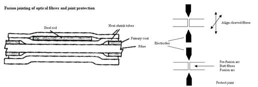
Connection losses from 0.1 dB to 0.3 db can be overcome by some connection methods. Manual control of connections is possible but requires great skill. Automatic control equipment is very expensive, but because the control is computerized, the results are recorded many times and achieved with high precision The cost of connection resources may not be available in some applications and a few proprietary mechanical connections. These mechanical connections are often used in ceramic capillary tubes to hold and align fibers. In this way, connection losses from 0.1 dB to 0.3 db are prevented. The sensitivity of SM fibers to line up is higher than MM fibers.


About Samm Teknoloji
Fiber Optic Cable Manufacturer
Being a Turkish fiber optic cable manufacturer and an efficient supplier for Europe, Asia and America, SAMM Teknoloji joined the global market with very high potential. SAMM designs and manufactures a wide variety of fiber optic cable types optimized for fixed or mobile networks that can be used in indoor and outdoor environments. SAMM offers reliable, cost-effective optical products to meet the needs of customers with innovative products developed and tested in accordance with international standards.
Fiber Optic Assemblies Producer
As a fiber optic cable assemblies producer and supplier in Turkey and an optical assemblies supplier for Europe and Asia, Samm Teknoloji has been providing high-quality and reliable fiber optic cable assemblies since 2006. Due to our fully equipped production facilities, laboratories and long-term expertise in fiber optics, we are able to produce a first class fiber optic assemblies portfolio that ensure the highest level reliability. Therefore, one of the main priority is the ongoing expansion and advancement of the manufacturing capabilities.
Data Center Solutions Producer
As a Turkish producer of future-ready fiber optic data center equipment, SAMM Teknoloji produces UHD ultra high density MTP/MPO panels and cassettes, modular panels and cabling raceways. SAMM Teknoloji has also kept pace with the accelerating spread of Cloud Computing, which has increased the need for mega Data Centers. SAMM provides Data Center solutions and products that suit all structures with high data storage density, data traffic and data security.