
 14 December 2020
What is Fiber Optic?
Contents
- Fiber Optic Cable
- Fiber Optic Cable Construction
- Fiber Optical Cable Coating Materials
- Fiber Optic Cable Coating Color Codes
- Commonly Used Fiber Connectors
1.Fiber Optic Cable
1.1.What is a Fiber Optic Cable?
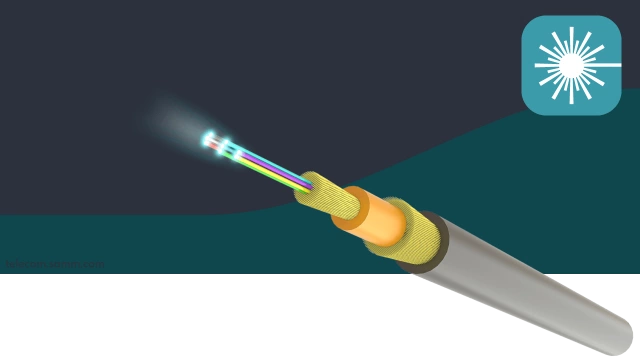
A fiber optic cable contains one or multiple optic fibers that are coated by several protective layers and are used to transfer light signals. The main purpose of fiber optic cables is speed and bandwidth because light signals can transfer a huge amount of data in less time, compared to copper netowork cables, which transfer electrical signals.
Optic fibers consist of glass or plastic cores in cladding tubes made of the same material; together, the core and the cladding tube are as thin as a human hair and the core is extremely clear that light signals can be perfectly transferred through it. A fiber optic core cannot possibly be handled on its own, which is why it is always surrounded by a color coded buffer tube. These optic fibers are usually reinforced by a strength element layer made of glass fibers or Kevlar, which is always covered by a protective color coded outer sheath jacket.
The type and quantity of fibers; in addition to the type of core, cladding, strength element and outer protective sheath jacket; differ from one cable type to another; depending on usage, distance and the surrounding environment where the cable is meant to be installed. Hence, there are many types of fiber optic cables for various installation areas like indoor, outdoor, underground or aerial overhead.
What are Fiber Optic Cables used for?
Fiber optic cables can directly connect two devices but they are usually used to connect between networks through patch panels and communication equipment. Fiber optic cables are used in numerous applications that require a wide bandwidth connection to transfer audio, video and data almost instantly. They were first used for military, government and broadcast applications but they have become very common in commercial, industrial and even residential internet providing applications. Applications of fiber optic cables are limitless and here are some examples:
- Closed circuit television systems
- Data transmission
- LAN & WAN and multimedia applications
- Connection between power plants
- Connecting active network devices at high speeds at long distances
- Advertising panels
- Medical devices
- Nuclear power plants where radioactive rays can affect electronic signals
- Point-to-point security applications where electrical noise is present
2.Fiber Optic Cable Construction
2.1.What is a Fiber Optic Cable made of?
A fiber optic cable usually consists of four elements: light transferring fibers, inner protective acrylic coating tubes, a purposefully constructed strength element layer and a protective outer sheath jacket.
First, the fibers are the inner and the actual effectual element in a fiber optic cable. Although the inner optic fibers are micrometers thin they consist of three layers on their own. The center core is the actual medium through which the light is transferred, and it has precisely selected characteristics to be extremely clear and efficient. Every optic fiber core has a cladding that provides a lower refractive index and ensures the light is reflected and kept inside the core. The cladding layer is always stuck to optic core and they cannot be separated by any hand tool. On the other hand, the third acrylic buffer layer of an optic fiber can be removed and it serves the purpose of basic protection and support and does not contribute to the light transfer process. In addition to that, the acrylic buffer is usually color coded to provide easier handling of multiple fiber optic cables, which might contain hundreds of fibers depending on the purpose of the cable.
Second, the middle coating buffer tube is inner protective layer, which can be a single loose tube that contains all the optic fibers loosely inside of it like outdoor highly resistant fiber optic cables, or can be multiple buffer tubes that contain and protect each fiber individually like indoor high performance fiber optic cables. In multiple fiber tight buffer cables, the buffer tubes with the fibers inside them are wrapped is a specific pattern around an inner supportive core element, in an SZ layout to provide equal distribution and easy access of fibers.
The third element of a fiber optic cable is the strength element. The strength element has a lot of material options like braids of Kevlar or glass fiber or a metal armor, non-metal armor or gel; and has layout variations of grouping the fiber inner buffer tubes in single shells or multi-shells. The strength element layer determines the tension support of the cable and flexibility, and it is used to determine the built of the fiber optic cable; whether it is tight, semi-tight, loose, armored or water resistant.
The fourth outer layer of fiber optic cables it the outer protective sheath jacket. It mainly protects the fiber optic cable from the conditions of the surrounding environment. If the cable is made for outdoor usage it can be resistant to UV sun rays, water, pressure and tension; and if it was made for indoor usage it is usually very reflexive and has a high performance.
These four elements that establish one fiber optic cable may be a bit different from one cable type to another, from one manufacturer to another and they are different also according the type of the intended termination point or connector of the fiber optic cable; which means the possibilities with fiber optic cables is limitless and live up to the hype and connection speeds they are made for.
2.2.What are the core dimensions of an Optic Fiber?
Because the core and cladding are always together as one unit, the measurement standard is always determined by the diameter value of both elements as a ratio in micro meters The main core and cladding standards are 62.5/125μm or 50/125μm for multi-mode fibers and 9/125μm for single-mode fibers. The outer acrylic is variable and the manufacturer can choose its thickness and color. The below illustration demonstrates a section of one fiber of all three standards.
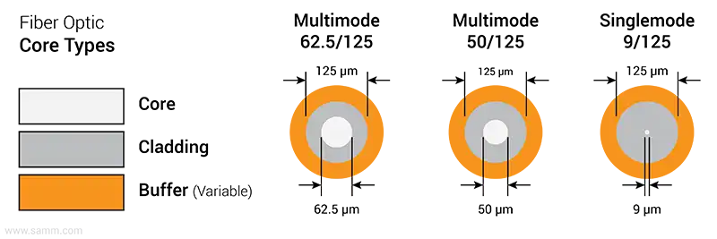
2.3.Fiber Optic Core Types
As mentioned above, there are two types of optic fibers according to the number of simultaneous signals, Multi-mode and Single-mode.
Multi-mode optic fibers have 125μm of cladding around a 50μm or 62.5μm core. This inner core diameter is relatively big enough for light to travel through it in multiple line spreads at the same time and in various reflection angles. Because the light in Multi-mode fibers is reflected or refracted millions of times, before it reaches the end of the fiber, the distance it travels is actually longer than the fiber itself and causes a delay in delivery, which is called ‘Dispersion’.
Single-Mode optic fibers have the same cladding diameter 125μm but have a very tiny 9μm core. This extremely thin core allows the transmission of only one spread line of light, which means a Single-mode fiber is a single path that allows only one light beam to travel through it. However, because the core is very thin the light travels in it with virtually no refraction angles, which means the distance the light travels in it is the same length of the actual fiber and arrives quicker than in Multi-mode fibers and with less dispersion delay.
2.3.1.Multi-Mode Fiber
Multi-mode fibers have two main standards according to the diameter of the layers (core, cladding, buffer) like this: first there is the 62.5/125/250micron and second there is the 50/125/250micron; and the most suitable wavelength to transmit infrared laser beams through them is between 850 and 1300 nanometers.
On the other hand, the production cost of Multi-mode fibers is more convenient than Single-mode, however they have a relatively higher light signal loss than Single-mode cabling. For all these factors, Multi-mode fiber optic cables are usually preferred for data transmission in "Local Area Networks" where the connections are multiple, the distance is short and end user handling is accounted for.
In addition, Multi-mode fiber-optic cables do not need high-precision connectors because the relatively larger core diameter allows for a larger margin of error. Hence, Multi-mode connectors, equipment, LED light sources, and sensors are usually more economical and practical.
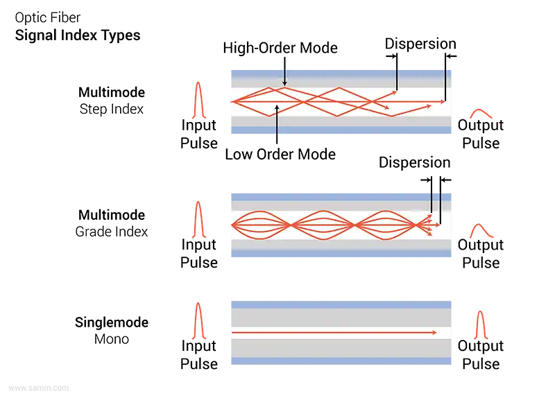
Multimode optic fibers can also be divided into two groups, according to the light signal index structure, the Step-index Multi-mode fiber and the Graded-index Multi-mode fiber.
2.3.1.1. What is Step-Index Multi-Mode Fiber?
Step-index optic fiber has a core with one unified density and one simple refraction index degree that contrasts with the density and the refraction degree of the cladding, thus when light beams travel through a Step-index optic fiber core, they travel in straight lines inside the core and get reflected each time they hit the inner wall of the fiber cladding; in other words, light beams travels through Step-index fibers in a zigzag motion. That is why the fiber core is relatively wider, which allows many light beams to be pushed into first end opening at many variant angles. However, if the light is beamed into the core in an angle higher than the critical reflection angle the light beam does not get reflected by the cladding but rather refracted and goes through the cladding to hit the inner wall of the buffer layer and gets lost completely.
In addition, because the light beams can enter the Step-index Multi-mode fiber at variant angles the total travel distance is different from one to another and the end delivery Dispersion delay is long and rather variable. Step-Index Multi-Mode can transfer data at bandwidth that rates from 10 to 50 MHz/Km.

2.3.1.2.What is Graded-Index Multi-Mode Fiber?
Graded-index optic fiber has a core with multiple layers within it each layer has a slightly different density and refraction index degree. A Graded-index fiber core has 50 to 400 layers, the inner density and refraction index degree is lowest at the center and highest at the edge of the core; the density increases with each layer from the center to the outer layers, and the refraction index degree increases in the same manner. That is why when a light beam travels through a Graded optic fiber core, it gets refracted multiple times with in the core itself, and travels in a symmetrical wavy line inside the core and may not even reach the inner wall of the fiber cladding depending on the angle, at which it enters the core. That is why the fiber core is relatively wider, which allows many light beams to be pushed into first end opening at many variant angles. However, if the light is beamed into the core in an angle higher than the critical reflection angle the light beam does not get reflected by the cladding but rather refracted and goes through the cladding to hit the inner wall of the buffer layer and gets lost completely.
On the other hand, although light beams can enter the Graded-index Multi-mode fiber core at variant angles, the all meet at node points in the middle with each wave. In addition, due to the symmetrical waves of light the Dispersion delay is not very long and its value varies in a small common range. Consequently, Graded-Index Multi-Mode fibers can transfer data at bandwidths that range from 200-300 MHz/Km to 5-6 GHz/Km, which is extremely higher than Step-index fiber.

2.3.1.3.What are the Advantages and Disadvantages of Multi-Mode Fiber?
| Multi-Mode Fiber Optic Advantages | Multi-Mode Fiber Optic Disadvantages |
|---|---|
| Due to the larger core diameter the fiber ends are more easily aligned during fiber termination, which provides shorter termination times. | Due to their limited speed, they are particularly preferred for large-scale applications. |
| The connectors, components and active elements used are more economical than Single-mode ones. | Multi-mode cables are thicker and their prices are twice as expensive as single-mode cables. |
| Cheaper LEDs light sources and sensors are used for light transfer. | Access distances are very short compared to Single-mode cabling. |
2.3.1.4. What are Multi-Mode Fiber Types?
Multi-mode fibers were first used without any standard, each manufacture had different diameters and different connectors, Multi-mode fiber was optimized differently for different networks and different light sources.
In the 80s, the telecommunication industry unified the standard and everyone started focusing on the 62.5/125μm Multi-mode fiber standard and the 50/125μm was only used for radio telecommunications instead of Single-mode fiber. Later, the 62.5/125μm standard was called OM1, and it was only capable of 100 Mb/s bandwidth for a distance of 300 meters.
In the 90s the OM2 50/125μm standard was reintroduced with a higher 1 Gb/s bandwidth and a maximum distance of 600 meters. Then in 2002 the OM3 emerged, allowing the first 10Gb/s fiber optic networks but for only 300m distance.
Then, in 2009, the OM4 standard started to be used, at first it improved the distance over the OM3 to be 400m at 10Gb/s but then it got upgraded to transfer at 40Gb/s and 100Gb/s but for a distance around 100-150m. OM4 and OM3 stayed the main standards for years, especially for data center applications.
Finally, the OM5, which started in 2014 but was not officially a standard until 2016, was created to be more economical solution than the OM4 and introduced multiple channels in one fiber.
OM1
- Orange color
- Core Size - 62.5um
- Data Rate - 1GB @ 850nm
- Distance - up to 300 meters
- Apps - Short-haul Networks, Local Area Networks, and Private Networks
- 62.5 / 125 Multi-Mode Fiber Cable
OM2
- Orange color
- Core Size - 50um
- Data Rate - 1GB @ 850nm
- Distance - up to 600 meters
- Usually used for shorter distances
- 2x Distance Capacity of OM1
- Apps - Short-haul Networks, Local Area Networks, and Private Networks
- OM2 Fiber Optic Multi-Mode Cable

OM3 - Optimized Multi-Mode with Laser
- Color - Turquoise
- Core Size - 50um
- Data Rate - 10GB @ 850nm
- Distance - up to 300 meters
- Uses less speed mode, providing increased speeds
- Can run up to 100GB of 40GB or 100GB using the MPO connector
- Applications - Larger Private Networks
- 10Gigabit Laser Optimize OM3 Fiber Optic Cabling
OM4 - Optimized Multi-Mode with Laser
- Color - Violet
- Core Size - 50um
- 10Gb / 40Gb / 100Gb
- Distance and Data rate: 400m @10Gb / 150m @40Gb / 150m @100Gb
- Up to 150GB up to 100 meters using the MPO connector
- Applications - High Speed Networks - Data Centers, Financial Centers and Corporate Campuses
- OM4 50μ-Multi-Mode 10Giga / 550m Optimized Cables
What is OM5?
Basically, the OM5 is made for 40Gb/s and 100Gb/s bandwidth; however, it uses multiple wavelengths (850nm, 880nm, 910nm, and 940nm) and uses a new technology called SWDM (shortwave wavelength division multiplexing). This technology allows the optic fiber to have multiple channels within the same core distribute the bandwidth up to four connections. This means that one OM5 40Gb/s cable acts as 4 separate cables with the speed of 10Gb/s and one OM5 100Gb/s can be used as four 25Gb/s cables. This improvement reduced the cost of data center equipment and cabling, especially that is compatible with OM3 and OM4; and it introduced a new generation with multiple numbers of connections in one cable.
OM4 and OM5: What's the Difference?
First OM4 is meant to work with only 850nm and OM5 be used with 4 wavelengths (850nm, 880nm, 910nm, and 940nm). OM5 can use SWDM4 technology, which allows multiple laser channels with different wavelengths to be transferred through one fiber at the same time. SWDM4 technology can be applied on OM4, however it is not as optimized as the OM5 which can achieve 500m at 40G/s. The table blow demonstrates the differences in bandwidth and distance of OM4 and OM5.
|
Fiber Type |
OM4 |
OM5 |
|---|---|---|
|
10GbE |
400 m |
400 m |
|
40GbE |
150 m |
150 m |
|
100GbE |
150 m |
150 m |
|
40G-SWDM4 |
400 m |
500 m |
2.3.2. Single-Mode Fiber
A Single-mode optic fiber a regular cladding with 125μm diameter but has an extremely thin (8 to 10 μm) core, which transfers light beams on the same path. The light signal in Single-mode fiber gets slightly reflected along the fiber, only to stay aligned within the core. This means that the light travels a distance almost identical to the length of the fiber, with almost no dispersion delay and very low attenuation.
Since there is only one light mode, the core material is the main variable that changes the level of dispersion and keep high bandwidth, which can reach 100 TeraHz/Km. If a fiber cable has multiple Single-mode fibers the light signals travel through them and reach the end at almost the same time.
In addition, Single-mode fibers use longer wavelengths; from 1310 to 1650 nm, and have low propagation loss and almost no dispersion. Because the low loss and longer wavelength, single mode fibers provide high transmission rates with up to 50 times more distance than Multi-mode fiber.

2.3.2.1. What are the Advantages and Disadvantages of Single-Mode Fiber?
| Single-Mode Fiber Optic Advantages | Single-Mode Fiber Optic Disadvantages |
|---|---|
| Can be used for very long access system distances, up to 100 km. | Because of the smaller core diameter, Single-mode fiber manufacture need more time an effort. |
| It supports high bandwidths and high speeds up to 10Gbps for about 10Km. | Because it has a small core diameter, Single-mode connectors and pigtail cords are very expensive. |
| The price of a Single-mode fiber cable is half the price of a Multi-Mode cable. | Single-mode requires more expensive laser diodes rather than LEDs. |
| High performance over long distances makes it the only choice for fiber network distribution. | Single-mode fiber active equipment, accessories and conversion devices are very expensive. |
What are the types of Single-Mode Fiber?
The ITU (International Telecommunication Union) has classified many types of Single-mode fiber, since it was firstly used, according to many factors. What differentiates an optic fiber from another is the attenuation (fading) of a light pulse through the fiber; the highest bend limit before light pulses start to be dispersed; the PMD Polarization Mode Dispersion, which may occur when one Single-mode fiber is used to transfer two alternating signals and finally the water peak, which is the increase in attenuation after contamination of hydroxyl (OH) ions during the manufacture process.
Sadece tek bir mod olduğu için, model dispersiyon ile ilgili bir problem yoktur ve malzemenin seçimi, bant genişliğini arttıran kromatik dispersiyonu azaltabilir.Ancak yaklaşık 100.000 gigahertz ile sınırlıdır. Tek modlu fiber, "mod alanı çapı", çekirdeğin etkili boyutu ve 125 micron bir kaplama çapı olarak belirtilen, 8-10 micronluk bir çekirdek çapına sahiptir. Erbiyum katkılı tek modlu fiberleri, fiber amplifikatörlerde, sinyalleri yenilemek için çok uzun mesafeli ağlarda kullanılan cihazlarda kullanılır. Fiberler, DWDM sistemleri için uygun dalga boylarında bant genişliği için optimize edilir veya kromatik dağılımı tersine çevirir. Bu aktif fiber gelişimi alanıdır. Bu alanda gelişilmiş kablo türleri aşağıdaki gibidir;
G.652
G.652 is an NDSF (non-dispersion-shifted fiber), and it was the most common standard in the 1980s. G.652 is optimized for 1310nm wavelength, and it has a low water peak specifically reduced for 1400nm wavelength. Because G.652 fiber is the oldest, it has four different types:
| G.652A | ||
|---|---|---|
| Attenuation | 0.5/0.4 | dB 1310/1550nm |
| Macrobend | 0.5 dB | 1550nm |
| PMD | 0.5 ps/sqrt(km) | |
| G.652B | ||
|---|---|---|
| Attenuation | 0.4/0.35/0.4 dB | 1310/1550/1625nm |
| Macrobend | 0.5 dB | 1625nm |
| PMD | 0.2 ps/sqrt(km) | |
| G.652C | ||
|---|---|---|
| Attenuation | 0.4 dB | 1310-1625nm |
| 0.3 dB | 1383/1550nm | |
| 0.4 dB | 1310nm after hydrogen aging | |
| Macrobend | 0.5 dB | 1625nm |
| PMD | 0.5 ps/sqrt(km) | |
| G.652D | ||
|---|---|---|
| Attenuation | 0.4 dB | 1310-1625nm |
| 0.3 dB | 1383/1550nm | |
| 0.4 dB | 1310nm after hydrogen aging | |
| Macrobend | 0.5 dB | 1625nm |
| PMD | 0.2 ps/sqrt(km) | |
G.653
G.653 Single-mode fiber is dispersion-shifted, to minimize dispersion and attenuation at 1550nm wavelength. This technique allows the production of fiber optic cables with longer capabilities.
G.654
Single-mode G.654 fiber has zero-dispersion at 1300nm wavelength, cut-off shifted and loss minimized at 1550nm and optimized for use with wavelength around 1600nm
G.655
Single-mode G.655 fiber is classified as NZ-DSF (nonzero dispersion-shifted fiber), which has dispersion characteristics that suppress the growth of four-wave mixing, when using wavelength division multiplexing WDM systems. In addition, G.655 NZ-DSF fiber supports high-power signals and longer distances, as well as closely spaced DWDM (dense WDM) channels at rates of 10 Gbits/sec or higher. G.655 is optimized for WDM and long-distance cable runs such as transoceanic cables.
G.656
G.656 adds special characteristics to Single-fiber to achieve non-zero dispersion for wideband optical transfer.
G.657
G.657 adds bend-insensitive characteristics to Single-mode fibers.
- Flexible single mode fiber
- G.657.A1 (minimum 10.0 mm radius)
- G.657.A2 (minimum 7,5 mm radius)
- G.657.B2 (minimum 7,5 mm radius)
- G.657.B3 (minimum 5.0 mm radius)
2.3.3. Fiber Types and General Properties
| Table of Optic Fiber Types and General Properties (OM / OS refers to TIA types, B refers to IEC types, G refers to ITU types) |
||||
|---|---|---|---|---|
| Core/Cladding | Attenuation | Bandwidth | Applications/Notes | |
| Multi-Mode Step-Index | ||||
| @ 850/1300nm | @ 850/1300nm | |||
| 50/125 micron (OM2, G.651.1) | 3/1 dB/km | 500/500 MHz/km | GB Rated | |
| 50/125 micron (OM3, G.651. 1) | 2.5/0.8 dB/km | 1500/500 MHz/km | Optimized for 850nm VCSEL | |
| 50/125 micron (OM4, G.651.1 ) | 2.5/0.8 dB/km | 3500/500 MHz/km | Optimized for 850nm VCSEL, higher speed | |
| 50/125 micron (OM5) | 2.5/0.8 dB/km | 3500/500 MHz/km | Broadband MMF for WDM 850/950nm VCSEL at higher speed | |
| 62.5 / 125 micron (OM1) | 3/1 dB/km | 160/200/500 MHz/km | Local network fiber | |
| 100/140 micron | 3/1 dB/km | 150/300 MHz/km | Old | |
| Single-Mode | ||||
| @ 1310/1550nm * | ||||
| 9/125 micron ( OS1 B1.1 or G.652 ) | 0,4 / 0,25dB / km | HIGH!~ 100Terahertz | The most common single fiber for Telem / CATV / high-speed local area network. OS1 is the name of TIA-568 for SM fiber cable for building use with higher attenuation - 1dB / km. All SM fiber looks like low water peak fiber. | |
| 9/125 micron ( OS2 B1.2 or G.652 ) | 0,4 / 0,25dB / km | HIGH!~ 100Terahertz | Low water peak fiber. OS2 is a name of TIA-568 for wired SM fiber for outdoor use. | |
| 9/125 micron (B2 or G.653 ) | 0,4 / 0,25dB / km | HIGH!~ 100Terahertz | Distributed slip fiber | |
| 9/125 micron (B1.2 or G.654 ) | 0,4 / 0,25dB / km | HIGH!~ 100Terahertz | Cut-off and shifted fiber | |
| 9/125 micron (B4 or G.655 ) | 0,4 / 0,25dB / km | HIGH!~ 100Terahertz | Non-zero dispersion-shifted fiber | |
| 9/125 micron (G.657) | 0,4 / 0,25dB / km | HIGH!~ 100Terahertz | Corrosion-free fiber | |
| Multi-Mode Step-Index | ||||
| @ 850nm | @ 850nm | |||
| 200/240 micron | 4/6 dB/km | 50 MHz/km | LAN and Slow connections | |
Fiber Optical Cable Coating Materials
The fiber optic cable coating material is specific according to the required application. The built material affects mechanical support, UV radiation resistance, oil resistance, etc. In the beginning fiber optic cables had outer coating made of PVC, however it has started to be replaced by halogen-free alternatives, to meet the constantly developed health and safety regulations.
| Material | Halogen-free | UV Resistance | Description |
|---|---|---|---|
| LSFH Polymer | Yes | Low | Good for indoor use |
| Polyethylene (PE) | Yes | Yes | Good for outdoor applications |
| Polyurethane (PUR) | Yes | Yes | Extremely flexible cable |
| PBT | Yes | Medium | Good for indoor use |
| PA | Yes | Yes | Indoor and outdoor use |
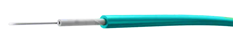
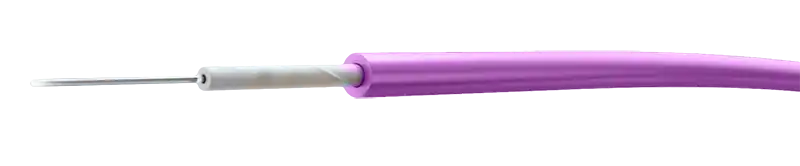
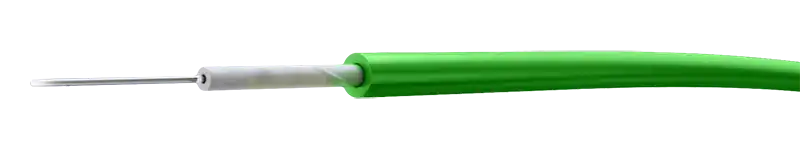
Fiber Optic Cable Coating Color Codes
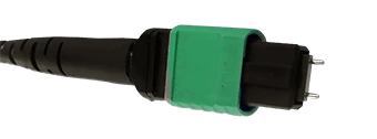
Fiber optic cables used in indoor and outdoor areas are often color-coded, in order to indicate the type of fiber used within them. The voltage and stress reduction fiber connector boot, which prevents the fiber end from over bending, is also color-coded to indicate the connection type. In addition the plastic shell of connectors (such as an SC connector) is also typically considered a color-coded jacket.
The standard color codes for jackets or boots are most commonly similar to the b list:
| Outer Sheath Coating Color | ||
|---|---|---|
| Color | Description | |
| Orange | Multi-Mode fiber optic | |
| Turquoise | OM3 and OM4 10G laser optimized 50/125 μm Multi-mode optic fiber | |
| Violet | OM4 Multi-mode optic fiber | |
| Yellow | Single-Mode optical fiber | |
Commonly Used Fiber Connectors
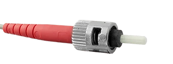
| Connector Type | ST |
|---|---|
| Coupling Mechanism | Twisted on |
| Fiber Type | Single-mode/Multi-mode |
| Ferrule Type | PC, UPC |
| Fiber Count | 1 |
| Typical Applications | LAN |
| Comment | Switch |
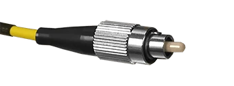
| Connector Type | FC |
|---|---|
| Coupling Mechanism | Screw |
| Fiber Type | Single-mode/Multi-mode |
| Ferrule Type | PC, UPC, APC |
| Fiber Count | 1 |
| Typical Applications | Data and Telecommunication |
| Comment | Switch |

| Connector Type | SC |
|---|---|
| Coupling Mechanism | Pluggable |
| Fiber Type | Single-mode/Multi-mode |
| Ferrule Type | PC, UPC, APC |
| Fiber Count | 1 |
| Typical Applications | CATV, Test , Equipment |
| Comment | Switch |
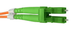
| Connector Type | LC |
|---|---|
| Coupling Mechanism | Pluggable RJ45 style |
| Fiber Type | Single-mode/Multi-mode |
| Ferrule Type | PC, UPC, APC |
| Fiber Count | 1 |
| Typical Applications | Gigabit Ethernet, Video, Multimedia |
| Comment | Small Form Factor (SFF) |
| Connector Type | MU |
|---|---|
| Coupling Mechanism | Pushing |
| Fiber Type | Single-mode/Multi-mode |
| Ferrule Type | PC, UPC, APC |
| Fiber Count | 1 |
| Typical Applications | Medical, Military |
| Comment | Small Form Factor (SFF) |
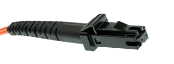
| Connector Type | MT-RJ |
|---|---|
| Coupling Mechanism | Pluggable RJ45 style |
| Fiber Type | Single-mode/Multi-mode |
| Ferrule Type | N/A |
| Fiber Count | 2 |
| Typical Applications | Gigabit Ethernet, Asynchronous transmission Mode (ATM) |
| Comment | Only Key Aligned coupling |
| Connector Type | MPO/MTP |
|---|---|
| Coupling Mechanism | Pushing |
| Fiber Type | Single-mode/Multi-mode |
| Ferrule Type | N/A |
| Fiber Count | 4, 8, 12, 16, 24 |
| Typical Applications | Active Transceiver, O/E Module Connections |
| Comment | Only Key Aligned coupling |


About Samm Teknoloji
Fiber Optic Cable Manufacturer
Being a Turkish fiber optic cable manufacturer and an efficient supplier for Europe, Asia and America, SAMM Teknoloji joined the global market with very high potential. SAMM designs and manufactures a wide variety of fiber optic cable types optimized for fixed or mobile networks that can be used in indoor and outdoor environments. SAMM offers reliable, cost-effective optical products to meet the needs of customers with innovative products developed and tested in accordance with international standards.
Fiber Optic Assemblies Producer
As a fiber optic cable assemblies producer and supplier in Turkey and an optical assemblies supplier for Europe and Asia, Samm Teknoloji has been providing high-quality and reliable fiber optic cable assemblies since 2006. Due to our fully equipped production facilities, laboratories and long-term expertise in fiber optics, we are able to produce a first class fiber optic assemblies portfolio that ensure the highest level reliability. Therefore, one of the main priority is the ongoing expansion and advancement of the manufacturing capabilities.
Data Center Solutions Producer
As a Turkish producer of future-ready fiber optic data center equipment, SAMM Teknoloji produces UHD ultra high density MTP/MPO panels and cassettes, modular panels and cabling raceways. SAMM Teknoloji has also kept pace with the accelerating spread of Cloud Computing, which has increased the need for mega Data Centers. SAMM provides Data Center solutions and products that suit all structures with high data storage density, data traffic and data security.